| Dave Higgins Consulting Strategic Technology Consulting and Enterprise Architecture |
Home | What's New | What's Old | Articles | Associates | Interesting Links | Cool Stuff |
Warnier Flowcharts
©Copyright 1990-2002 Dave Higgins. All Rights Reserved.
Introduction
Flowcharts have been used for many years to graphically depict
the organization of logic in computer programs. In his Logical
Construction of Programs (L.C.P.) technique, J.-D. Warnier defined a rather different flowcharting
method that was used to illustrate the organization of data
structured programs. Simpler and far more elegant than
traditional flowcharts, these diagrams, which we dubbed Warnier
Flowcharts, are a large part of what first attracted the interest
of Ken Orr and myself in Warnier's work. Our interest and
investigation of Warnier's methods led to our own description of
a data structured information engineering method, which has come
to be popularly known as the Warnier/Orr methodology. While our
hybrid Warnier/Orr methodology does not stress the use of these
flowcharts, Warnier's original diagrams remain an interesting
program design tool, and have important applications in
reengineering the logic of old, unstructured programs.
Warnier's pioneering work in data structured design methods was conducted primarily in the 1960's and early 1970's through the auspices of CII-Honeywell Bull in Paris, France. Warnier and his group developed three primary analysis and design methods: Logical User Requirements (L.U.R.), Logical Construction of Systems (L.C.S.), and Logical Construction of Programs (L.C.P.). While quite popular in Europe for a time, Warnier's methods were never enthusiastically embraced in the United States. Although our Warnier/Orr approach earned some measure of acceptance in the U.S., Warnier's original work remains largely unknown. This is unfortunate, as his insights into the analysis and design process are thoughtful and provocative.
One aspect of Warnier's work that we will examine in this paper is the flowcharting method used in L.C.P. Although deceptively simple, it is also quite a powerful diagramming method. While Warnier originally used it as a bridge between a data structure representation and program code, we have found that his flowcharts can also be interesting in the investigation of old programs.
Core
Constructs
At the core of Warnier's flowcharting method lies the concept of
a logical sequence of activities. Often abbreviated
"l.s.," a logical sequence is any group of instructions
executed the same number of times and under the same conditions.
It is shown on a Warnier flowchart as a single box.
![]()
Figure 1: A Logical Sequence
In other words, a logical sequence is a "black box" of one to many instructions that represent a meaningful area in the program code. Warnier flowcharts of arbitrary complexity are created (figuratively) by beginning with a single logical sequence representing the entire program, and then looking inside to expose deeper program structure. In actual practice they are created from an examination of the data structure of the program. Unlike traditional flowcharts where charting symbols can be used in any combination, Warnier allows only two logical structures inside a logical sequence: repetition and alternation. Repetition is a traditional DoUntil loop (a loop executed from one to many times), while alternation is always expressed as a simple, binary alternative.
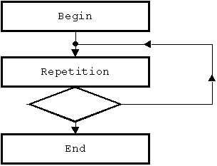
Figure 2: Repetition
A repetitive structure always contains exactly three logical sequences: the l.s. representing the group of actions done once before the repetition, the l.s. representing the group of instructions that is repeated one to many times, and the l.s. representing the group of instructions that is done once after the repetition. The decision diamond is always shown attached to the bottom of the repeating logical sequence: this is because the test ("if" statement) to determine whether to "loop" or to "quit" is always the last statement in that logical sequence. The dot where the "loop" branch intersects with the "fall through" branch is called a junction.
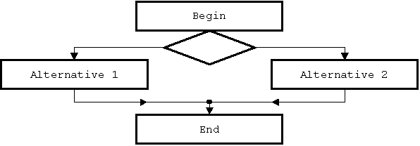
Figure 3: Alternation
An alternative structure always contains exactly four logical sequences: the l.s. done once before the alternative, one l.s. for each of the two mutually exclusive alternatives, and the l.s. that is done once after the alternative. Like the repetitive structure, it also contains one decision (attached to the bottom of the beginning logical sequence) and one junction (where the two alternative paths rejoin).
Compound
Structures
Two other structures often commonly defined as "structured
programming" constructs, the DoWhile loop and the Case
statement, are not fundamental constructs on a Warnier Flowchart,
but are instead compound structures built upon the two
fundamental constructs.

Figure 4: The DoWhile Construct
The DoWhile construct is basically a repetition inside one leg of an alternative. Warnier felt very strongly that the DoWhile should not be used as a fundamental construct if program maintainability is a concern. Consider the following flowchart of a DoWhile loop.

Figure 5: Traditional DoWhile Loop
Implemented in this fashion, there is no inherent place (logical sequence) to put instructions that are to be done only if the loop is bypassed, nor are there places to put instructions that are only done once at the beginning of the loop nor once at the end. This complicates any maintenance that may have to take place on the logic of the program at some point in the future, thus their use was discouraged in L.C.P.
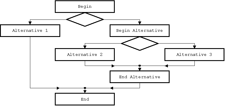
Figure 6: A Case Structure
A case statement (in this case the choice between three mutually exclusive alternatives) can be built up by "nesting" successive alternatives. These two figures also should begin to suggest to the reader how Warnier Flowcharts are in effect "grown" by doing successive replacements of logical sequences with lower levels of structure. In fact, Warnier Flowcharts can be categorized as to their level of complexity by how many such replacements are needed to "grow" the finished flowchart from a single logical sequence (considered "level 0"). The vanilla repetition and alteration structures are both "level 1" flowcharts, since each is built from the explosion of a single logical sequence. Both the DoWhile construct and the sample case structure shown in the figures above are "level 2" flowcharts, since each requires two substitutions from a single l.s. to create the flowchart. (In the DoWhile, the initial l.s. is replaced by an alternative, and the rightmost l.s in the alternative is replaced by repetition-in the case structure, the initial l.s. is replaced by an alternative, and the rightmost l.s. in the alternative is replaced by another alternative.) Needless to say, programs of arbitrary complexity can be built with a sufficient number of substitutions.
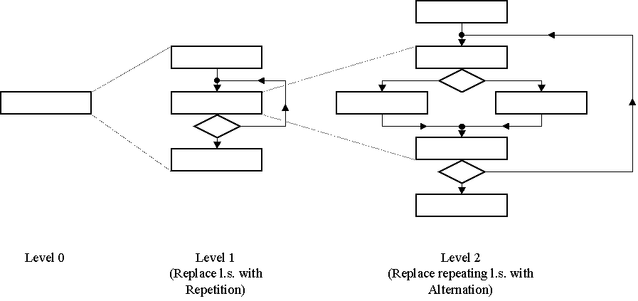
Figure 7: Expanding logical sequences to "grow" a more complex flowchart.
Since each successive substitution of repetition or alternation adds precisely one decision (shown by the conventional diamond symbol) and one junction (where one line of flow meets another), the level of complexity of any given Warnier flowchart can easily be determined by simply counting the number tests (or junctions). In practice, once the complexity level reaches the high teens, a program becomes difficult to represent with a single diagram. This can be alleviated by breaking the program design into several disjoint modules of code (remember that each logical sequence can represent a "subroutine" of arbitrary complexity).
Also because of their formation rules, certain program logic constructs are simply not possible to generate.
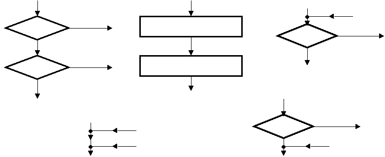
Figure 8: Impossible Constructs
On a Warnier Flowchart you can never find two logical sequences, two intersections, or two decisions in a row. Similarly, a decision can never directly precede or follow a junction. Also, the number of decisions will always be equal to the number of junctions. While not terribly important when creating Warnier Flowcharts for new program designs, understanding these formation rules is important if you are attempting to translate existing program logic into Warnier Flowchart form. One other formation rule of note: if you follow the columns of the logical sequences created by substituting repetitive structures and alternative structures, a Warnier Flowchart always ends in the same column in which it began. The patterns of flowcharts created using these formation rules are visually quite striking, and one of the first things we noticed when reviewing Warnier's work (our French wasn't very good, but we could tell from just the appearance of the flowcharts that he had to be doing something right!).
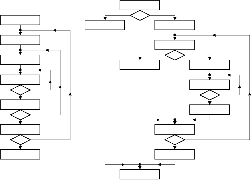
Figure 9: Sample Warnier Flowcharts
Home | What's New | What's Old | Articles | Associates | Interesting Links | Cool Stuff |
This web site and all
material contained herein is Copyright ©2002-2009 Dave
Higgins. All Rights Reserved. For additional information,
please contact me at: |